Extract Axis or Centerline from 3D Object
Use this dialog to extract an axis (centerline) or centerline from 3D objects in an inserted IFC model, DWG file, or triangle net in the application layer.
Where can I find the dialog?
In the terrain model drawing context menu, select Tools - Extract Centerline from 3D Object...
Method
Select the method for extraction:
- Extract axis – extracts a centerline based on the axis method. For pipes and similar objects, this will often give the most expected result.
- Extract centerline – extracts the centroid line. This method may be better suited for more general volume objects.
Using the Dialog
The function calculates a line through the 3D object and the quality of the line, indicating how well the straight line fits the 3D object.
You can set a quality requirement – only lines within the requirement will be placed on the result application layer. The calculated quality is also stored in the CL_Quality attribute.
Options
Automatic row detection – enables automatic detection of rows in the object.
Approximate radius – specifies the expected radius of the object. Used as an aid in the calculation.
Min point distance – minimum distance between points on the calculated line.
Quality limit – maximum allowed deviation between the line and the 3D object. Objects that exceed the limit are not included in the result application layer.
Copy Attributes
Select which attributes from the 3D object should be copied to the result line:
- All attributes – copies all attributes from the 3D object.
- Only attributes that exist in the application layer – copies only attributes already present in the result application layer.
- No attributes – no attributes are copied.
Result Application Layer
Select or create the application layer where the calculated lines will be placed.
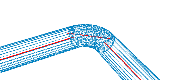
Example of a centerline with a bend