Road Design
All data related to road design is stored in an SFI model.
What is an SFI model?
The SFI model (SectionFile) is a general model for structures that follow a line. It is used for roads, water/sewage (trench), and tunnels, among other things, and in principle for any theoretical model that follows a centerline – for example river bank protection, embankment dams, and walls.
The icon for the SFI model's properties dialog can be found on the toolbar menu:

SFI properties
When you design roads in Gemini Terrain, you typically use the Parametric calculation method, and this is the method used in this chapter. With the parametric method, you define the road body using Road parameters, and the method supports dimensioning according to handbook N100 Road and Street Design.
Manual (tabular) method
Gemini Terrain also has a manual method, where the road body is defined using tables. It gives you full control over building the layers of the road body – you can, among other things, edit profiles manually and lock profiles – and was historically used mostly during construction and quantity tracking.
The method can now be run in automatic mode, which makes it more relevant for design as well. However, it has a limitation: you cannot dimension the road surface as you can with the parametric method. The manual method is described in more detail under Execution in the chapter Documentation of Quantities in Roads.
Work Process for Road Design
Procedure
The following procedure can be used to design a road:
- Define horizontal curvature
- Generate longitudinal profile
- Define vertical curvature
- Define the normal profile
- Generate cross-sections
- Perform mass calculation
- Export road model
Curvature and 3D Space
The road line is a curve in three-dimensional space. In Gemini Terrain, you work with the curvature separated in two planes:
- You construct the horizontal curvature in the map
- You construct the vertical curvature in the longitudinal profile
Horizontal and vertical curvature together form a space curve with three dimensions. Since you work with horizontal and vertical curvature separately, you must not forget that during planning you must ensure that the space curve has a smooth and rhythmic form.
Info
You can read more about good alignment, aesthetics, and optical guidance in handbook V120 Premises for Geometric Design of Roads.
Editing Designed Roads
When you have designed a road, you usually need to make some changes (revisions). Which steps you need to perform depends on what you want to change.
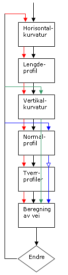
Color coding in the figure: red = steps that must be redone when the horizontal curvature changes, green = new mass calculation when the vertical curvature changes, blue = changes to the normal profile.
Horizontal Curvature
If you move the horizontal curvature, you may need to revisit all points again, marked in red in the figure above. A new longitudinal profile must be generated, the vertical curvature must be adapted to the new longitudinal profile that has become longer or shorter, the normal profiles must be adjusted (especially width extensions and cross slopes), and new cross-sections must be generated.
Note
These changes are only necessary in areas where the horizontal curvature no longer coincides with how the horizontal curvature was before editing started. In areas where the horizontal curvature coincides, the program performs a calculation that preserves the original vertical curvature and road parameters by shifting them relative to the new profile numbering.
This applies to both ordinary editing and editing with grips. If the centerline is shortened at the beginning (for example, by deleting profile 0-100), the profile numbering is shifted so that the parameters in the deleted area are also preserved.
Important
Note that you should still check the longitudinal profile and vertical curvature, as well as generate new cross-sections to recalculate the road surfaces.
Also note that if you need to use the Reverse direction function on the horizontal curvature, so that the original starting point becomes the new endpoint, the vertical curvature adapts to this automatically. Most road and tunnel parameters also adapt automatically and are placed on the correct side, but note that broken slopes and tunnel blocks must be added again.
Example
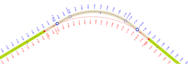
In the example below, the blue line illustrates the original horizontal curvature, while the red line is the edited horizontal curvature. Here, vertical curvature and road parameters will be preserved in the green areas (due to coincident geometry).
Vertical Curvature
If you change the vertical curvature, it is sufficient to run a new calculation for documentation of new masses, marked in green in the figure above.
Important
The program automatically runs a calculation when you finish editing the vertical curvature. This means the road body is updated when you switch to the cross-section drawing windows, plan, or 3D model view.
Cross-Section
Regarding the normal profile, you have two different situations, marked in blue in the figure above:
- If you only change values for the parameters, it is sufficient to run a new road calculation for documentation of new masses
- If your changes involve new intermediate profiles, you must also generate cross-sections to capture these
Road Dimensioning Library
Roads are, according to handbook N100, divided into different dimensioning classes. These set requirements for:
- Road widths
- Curvature and general technical standard
- Cross-section to shoulder edge
- Alignment parameters
- Intersection solutions and exits
- Solutions for pedestrians and cyclists
- Public transport facilities
- Lighting systems
Furthermore, the handbook contains, among other things, design tables for each dimensioning class.
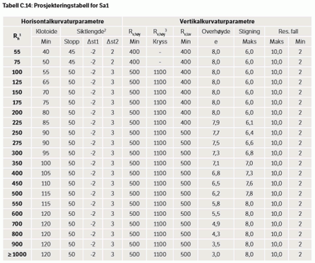
Example of design table from handbook N100
The calculation basis for these and other requirements can be found in handbook V120 Premises for Geometric Design of Roads. The formula framework and basic parameters described in this handbook are implemented in Gemini Terrain's road dimensioning library.
Info
You can read more about the road dimensioning library here.
This means that the dimensioning library does not look up values in tables, but calculates the values "on the fly". This also means you get exact values and not rounded values as in the tables.
Check Against Standard
When you construct the road line, you get "on the fly" notification if you violate the requirements for the road class. You can also check if the road complies with current regulations after it is fully designed.
When you check the road line using Check against standard, both vertical and horizontal curvature are checked, as well as the resulting gradients.
Note
The normals are a starting point (and framework supplier) for road design. You must decide whether the road line from a professional perspective needs to be changed to satisfy road standards. It is perfectly possible to ignore messages from this check.
Further Learning
See the example collection for implementation: