Mass Calculation
Gemini Terrain uses the cross-section method for road mass calculations. This method is described in more detail in Cross-Section Calculation Method. This chapter covers mass balance and the predefined mass types for roads.
Correction Factors
To achieve calculation results as close to reality as possible, you must correct the calculated masses for factors such as mass expansion during rock blasting and shrinkage during extraction, transport, and placement.
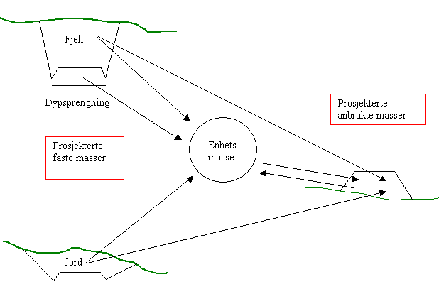
Figure: Correction factors for mass calculations
Mass Balance
During the design phase, the most important task is to calculate the mass balance. The mass balance is determined by comparing the mass requirement (designed placed masses) with the available masses (designed solid masses) along the road alignment.
It is common to present the masses graphically using a bar chart (mass diagram). The height of each bar is determined by the calculated volume (\(V = A \cdot L\)). The volume is given as unit mass or as designed placed masses (pam³).
Mass Diagram
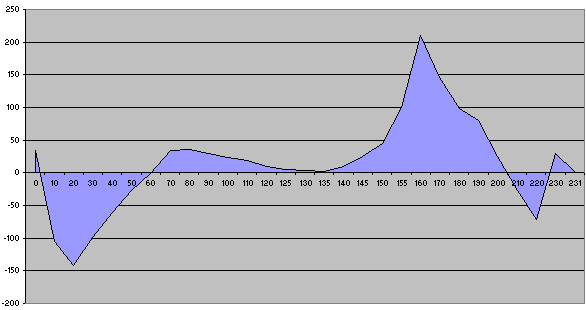
Figure: Bar chart showing the mass balance
Info
Accumulated mass balance, that is, the sum of all masses from the start of the road to the point where the volume is plotted on the curve, provides a better overview.
Accumulated Mass Balance (Mass Profile)
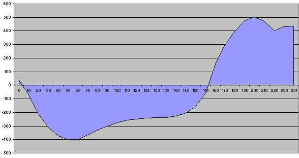
Figure: Graphical representation of accumulated mass balance
Predefined Mass Types
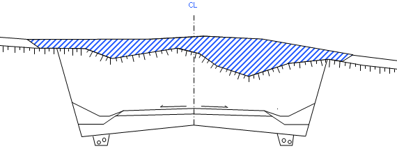
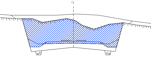
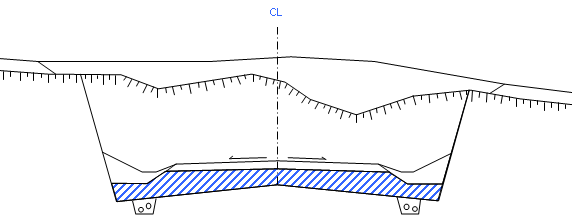
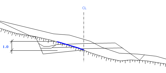
Gemini Terrain includes predefined mass types for automatic road calculations. The mass types are illustrated below.
| Description | Unit | Note |
|---|---|---|
| Soil cut | Volume | |
| Topsoil | Volume | |
| Topsoil fill | Volume | |
| Rock cut | Volume | |
| Deep blasting | Volume | |
| Area blasting | Area | |
| Fill | Volume | |
| Ground leveling for mass replacement | Volume | |
| Mass replacement | Volume | |
| Road surface | Slope area | |
| Road surface | Volume | |
| Base layer | Slope area | |
| Base layer | Volume | |
| Sub-base | Slope area | |
| Sub-base | Volume | |
| Soil cut | Slope area | |
| Rock cut | Slope area | |
| Fill | Slope area |
Soil Cut
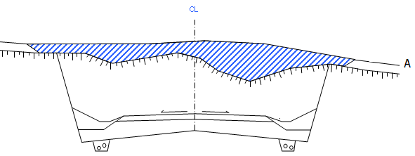
Figure: A = Soil
Topsoil
Rock Cut
Deep Blasting
Area Blasting
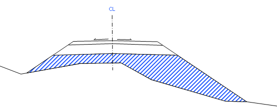
Fill
Next Step
Once the masses are calculated, you can export the road model to field. See the overall work process for road design.