Horizontal Curvature
First, let's briefly review the elements of a horizontal curvature. When constructing the road's horizontal curvature (centerline), we use the elements:
- Straight line (L)
- Circular arc (R)
- Clothoid (A)
The figure below shows an example of how the different elements are combined in the horizontal curvature.
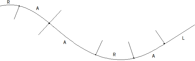
Figure: R = Circle, A = Clothoid, L = Straight line
Common Combinations
The most commonly used combinations:
- L-R-L
- L-A-R-A-L
- R-A-A-R (reverse clothoid)
- R-A-R (egg clothoid)
In municipal engineering, it is common to use only straight lines and circular arcs. It is important to construct the centerline as a continuous line with tangency between the elements.
Creating an SFI Model
Before you can start constructing the horizontal curvature, you must create an SFI model.
Procedure
- Activate the models tab.
- Select SFI models and choose Create... from the right-click menu.
- Click ..., select a template, and click OK.
- Enter the model name and click OK. The properties dialog for SFI properties opens.
- Click OK in the properties dialog.
- Line editing via the properties dialog is now started.
- Construct the horizontal curvature (the available functions are described below).

Note that the commands for line annotation and the road body for the surface are automatically inserted in the drawing.
Shortcut for a simple line
If you only want to create a line – for example to generate a cross-section – you can take a shortcut. Select  Horizontal curvature (line definition) from the Planning, design and execution toolset.
If you have selected a road class in the SFI model, the program uses the requirements from that class during editing. If you violate the road class requirements, the element is drawn in red.
Editing Methods: Properties Dialog and Grips
In Gemini Terrain, you can edit the horizontal curvature in two ways:
- Properties dialog – precise, value-based editing. You can press Cancel to undo the changes you have made.
- Grips (grip handles) – fast, dynamic editing directly in the map, especially effective on existing lines. Note that grips editing cannot be undone with Cancel.
 The icon to activate grips is on the toolbar.
 You can turn dynamic helper lines – dynamic annotation and helper geometry – on/off with the icon at the bottom left of the toolbar.
Hide the dialog with [Ctrl]+[D]
The properties dialog takes up a lot of space, and it can be useful to hide it while editing the geometry. Turn it on/off with [Ctrl]+[D]. [Enter] ends and saves the line (or click OK when the dialog is open). In editing mode, the various elements (straight line, radius, clothoid) are highlighted with colors.
The rest of this chapter describes editing via the properties dialog. In general, you can double-click an object to open the properties dialog.
Right Mouse Button Functions
When you press the right mouse button in the map, a menu appears with the functions for dynamic editing. All functions have a hotkey – learning these saves you many keystrokes. The functions are described one by one below.
 Insert point
This button activates the mode for inserting angle points.
When you create a new line, this mode is automatically activated. When it is active, you can insert new points by pointing and clicking the left mouse button in the map. In insert point mode, you can snap to helper lines/helper circles by holding [Ctrl].
When you insert new break points in the map, the program automatically adds a minimum rounding if a road class is selected. If you change the radius dynamically, the clothoid changes accordingly. If you violate the road class requirements during editing, the element is drawn in red. Note that clothoid/radius/clothoid is treated as one object, meaning you cannot insert a point between the clothoid and the radius.
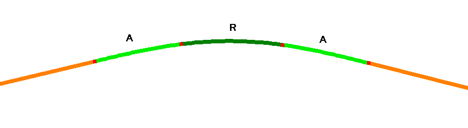
If you insert a point so that the angle change becomes small, the arc element disappears and the clothoids touch each other exactly. The radius at the point of contact increases with smaller angle change.
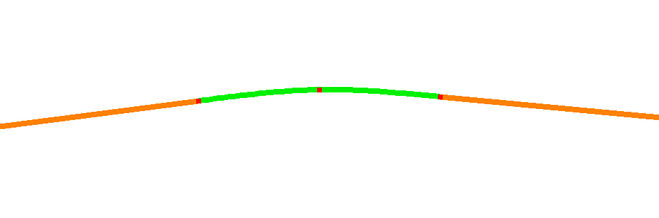
If you move the angle points so that the angle change becomes large enough, the radius returns. The radius is then taken from the clothoid system.
How to continue a line at the last point?
If you select the last point on the screen, it is marked with a small cross. If you activate the insert point function, the point is inserted in front. If you want to insert a point behind, you must point and click a bit to the side of the line. In other words, no point may be marked with a small cross. If you have the dialog open, you will see that the empty row below the last point is highlighted.
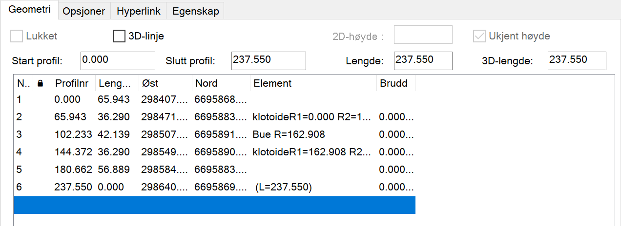
If you activate insert point in these cases, the new point is inserted behind.
When you select an element on the screen during editing, it is marked blue and its start point gets a small cross. If you then activate the insert point function, new points are inserted in front.
 Insert/change rounding
Use this option to manually insert roundings with or without clothoids at an angle point.
Select the point on the screen or in the dialog box (it is marked with a small cross), and the function is available on the context menu. Enter the desired radius, as well as any parameters for the clothoid in front and behind.
You can also change existing roundings. Select the arc or clothoid element on the screen or in the dialog (the element turns blue), and the function is available on the context menu.
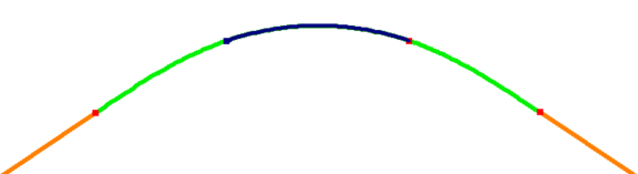
Note
You cannot insert roundings at the start and end points. If you want this, you can, for example, create a helper line circle and snap to it.
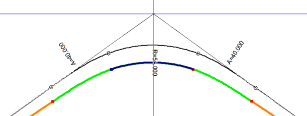
 Move dynamically via angle point
With this function, you can move a line dynamically via an angle point. Select the arc or clothoid element on the screen and choose the function on the right mouse button. The curve points update continuously as you move the line.
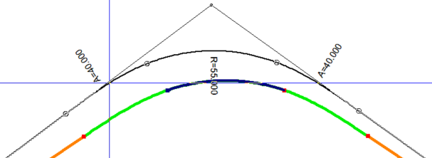
 Move dynamically via point on line
With this function, you can move a line dynamically via a point on the line. Select the arc or clothoid element on the screen and choose the function on the right mouse button. The curve points update continuously as you move the line.
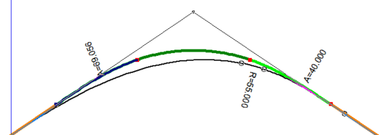
 Move clothoid endpoint dynamically
With this button, you can dynamically change the length of the clothoid. Select the clothoid on the screen and choose the function on the right mouse button.
 Move radius dynamically
With this button, you can dynamically change the size of the radius. Select the radius on the screen and choose the function on the right mouse button.
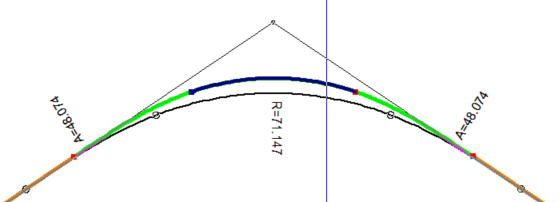
 Delete and recalculate roundings
With this option, you can delete roundings (R, A-R-A, etc.) and have the roundings in front and behind recalculated. The option is only active when you have selected a radius element on the screen.
Some Special Functions
 Add line length / Add arc length
With this function, you draw a new element with a given length and direction – either a straight line or an arc.
Add line length: You draw a line with a given direction and distance. If the previous element is a straight line, the same direction is suggested as default; if the previous element is an arc, the tangent direction is suggested.
Add arc length: You draw an arc with a given length. You must enter direction, arc length, and radius. The default direction is tangent to the previous element, so that you do not get a break in the line definition.
 Extrapolate line in 3D
With this function, you can extend a line in 3D. The function can, for example, be used to calculate the intersection point for piles when you have two known points on it. By selecting the first or last point on the line, you can extrapolate it by a given length.
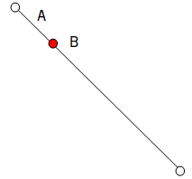
Figure: A = Length, B = First point
Next Step
Once the horizontal curvature is in place, you generate the longitudinal profile and construct the vertical curvature. See the overall work process for road design.